
Predictive Maintenance
Condition Monitoring on the High Seas
A worldwide special fleet designed for oil prospecting and exploratory drilling and able to make exploratory drilling even in the polar region is operating from Aberdeen Scotland. An essential part of a drilling ship is the main hydraulic system controlling the boring feed with the boring tower hydraulic cylinders, and at the same time compensates the effects of waves and sea-level change.
A drilling ship equipped with the Condition Monitoring (CM) system is 228 m long, 42 m wide and can drill down to a depth of 10 000 meters. The wave compensation system can compensate against waves of up to 7.6 m with full drilling power with the positioning of the drilling ship being controlled by “Dynamic Positioning” GPS-controlled software. The main hydraulic system has a total oil volume of 90 000 litres, out of which 16 000 litres is in the piping system and in drilling tower cylinders. The cylinder stroke is 24 m with a normal moving speed of 1.5 m/s and 2.5 m/s in fast action when the 29 hydraulic pumps give a flowrate of up to 33 000l/min.
Operating at sea requires special specifications from the hydraulic system, especially from the service and reliable spare parts availability point of view. A stoppage in the drilling work because of a failure in the hydraulic system could cause enormous costs; it is therefore important that the CM expert system controls the hydraulic system parameters 24/7/365.
The CM system consists of 31 optical particle counters, 31 pressure transducers, 26 flowmeters and 4 multifunctional oil condition sensors with the main function of the system being to monitor the condition of the hydraulic pumps. The system gives an alarm of pump failures, reports the operating time of pumps and gives information about the overall pump condition by comparing the current actual measured values to the measured values of a new pump, enabling advanced planning of condition-based and time-optimized maintenance.
Based on the real time measuring data and alarms from the hydraulic system, the CM system sends an automatic report of immediate service needs to the service per- sonnel, thus preventing expensive damages and additional failures and increasing the utilization rate. Service and maintenance operations can be optimized and the lifetime of components in a hydraulic system is increased.
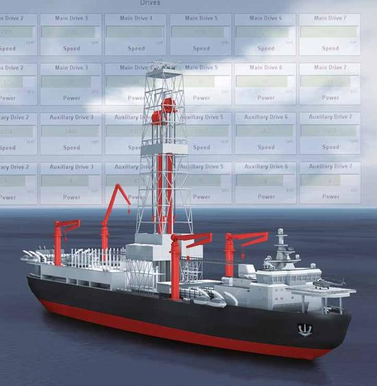
Figure 1. Drilling ship is ideal object for the Condition Monitoring System.
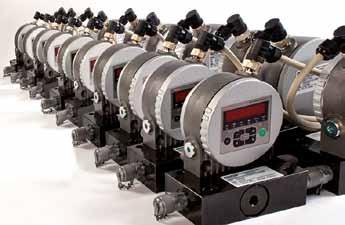
Figure 2. Particle counter assembly.
The sensor data is collected in a router in the hydraulic room for data processing and transferred to the main unit, which is installed in an isolated marshalling cabinet. The main unit consists of an industrial PC and condition-monitoring software to process and visualize the measurement data. The user interface is a touch screen panel installed on the main unit (figure 3), which can be individually tailored to meet each customer’s needs.
The visualization and naming of the pump groups is done according to customer specifications and names like “spare pump”, “main pump 1”, “main pump 2”, “servo pump” etc. are used in the user interface. The sensor values, alarm limits and alarms are shown for each pump group.
When the limit values have been reached or exceeded, the system sends an automatic message to the operator informing which sensor and in which measuring location triggered the alarm. Furthermore, the alarm will show up in “traffic lights” located in the hydraulic room or service centre. The stored measuring curves and limit values of each measuring point can be easily checked afterwards. Condition of the hydraulic system and necessary service actions can be eas- ily and quickly defined based on the measuring data and easy switching between online data and history data helps to compare the values.
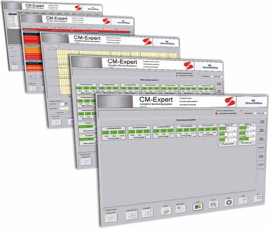
Figure 3. CM-Expert condition monitoring system user interface.
The user interface display can show the actual measured values both in numerical and graphical forms and the alarm and message system allows the user to find, define and compare the alarms and history data of each sensor. The alarm log shows alwaysopen alarms and messages and in addition the colour coding shows the condition of each group, which helps to find active alarms and messages. All alarms are stored in the alarm log and can be read at a later date (for example after a shift change, the next shift can check alarms, messages and comments during the previous shift).
A reliable condition monitoring system needs calibrated sensors, so there is a calibration test bench installed in each ship to ensure reliable and long sensor operation. A supplier’s specialized service technician maintains the system and calibrates all sensors once a year.
The CM-Expert condition monitoring system can be installed to most applications and sensors, for example in steel mills, paper factories, power plants, machine tools, mining and mobile applications.
Features of the condition monitoring system:
- Constant monitoring of the production media
- Automatic messaging of maintenance-relevant limits have been reached
- Immediate alarm when the limits are exceeded
- Early detection of the faults and prevention of “emergencies”
- Optimization of service intervals
- Reduction of maintenance and repair costs
- Prevention of the operation downtime and consequential damage
- Customer tailored user interface and operation.
 |
Robertus Koppies
Manager Condition |
Tagged condition monitoring, drilling, fleet, Robertus Koppies

Pingback: waterproofing
Pingback: TS TV Escorts from London