
Predictive Maintenance
Load measurement and analysis:
the supreme discipline in Condition Monitoring
Machines, systems, ships and motor vehicles are becoming more compact and powerful while at the same time becoming lighter. Electrical drive technologies are growing more dynamic. This leads to greater dynamic loads, which design engineers, system planners and mechanical engineers need to know about.
Vibration analyses are suitable for assessing machine conditions, identifying dominant vibration exciters and/or defining further measures for machine optimization based on in-depth analyses. To quantify the occurring loads, however, dynamic load measurements are required. PRÜFTECHNIK has developed mobile and online condition monitoring systems that can be used anywhere in the world for measuring loads quickly and flexibly, for analyzing load and strain conditions, and for acquiring advanced proprietary knowledge.
Operating histories, damage patterns and load analyses
Operating histories show that machines and systems, despite careful design and production, are affected by external factors that can impair their functionality or cause damage, defects, faults, weak points, disruptions and even failure. When damage occurs due to mechanical loads, it also becomes necessary to consider the dimensioning of the drive technology in use.
Initially, of course, operating histories provide some orientation. If a machine does not reach its intended power out put and/or achieve the desired qualities, its drive systems may be intended for smaller loads or other performance problems may exist in the system. If damage actually occurs, the damage patterns contain valuable information.
Forced fractures, for example, are often caused by malfunctions, seizures or overloads. Fatigue fractures and cracks can be caused by impermissible load vibrations or disturbing vibrations. Typical fatigue fractures or forced fractures in a universal joint shaft are shown in Figure 1.
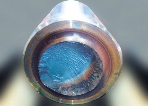
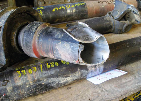
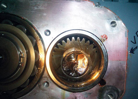
Fig. 1: Several damage patterns on machine components
In the construction of machines and plants, torques and bending moments are important mechanical load quantities for rotating components, and they allow the reduction of costs.
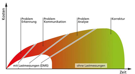
Fig. 2: Load measurements reduce the costs and time needed to find a solution and can be clearly displayed
Load measurements consist of a static (temporally constant) and a dynamic part (cyclic or fluctuating load). In the case of regular load variations, the amplitude and frequencies of the dynamic aspect are of interest.
An additional load analysis can be applied to more quickly analyze and communicate the causes of atypical damage, as well as to reduce impermissible dynamic loads through knowledge, experience and/or increased precision. Reduced dynamic loads mean that machine components that are subject to complex loads during rolling, friction and impact processes will “run” better and “reward” the owner with a longer service life.
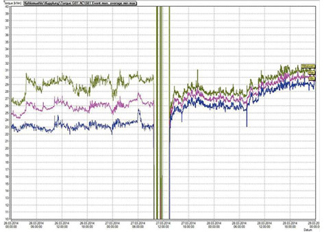
Fig. 3: Torque values before and after optimization on a large mill drive
Figure 3 illustrates this for a large mill drive system before and after an optimization was implemented. The minimum, mean and maximum torque values are shown in kNm, each recorded at an interval of 5 minutes. Reduced load variations can be detected starting on 03/27.
Dimensioning of drive technology

Fig. 4: Type plate of a motor with the rated parameters
Drive technology is designed on the basis of information contractually agreed between the plant or machine manufacturer and the respective component manufacturer. In the case of existing machines, the first source of information concerning loads is the type plate, which contains values such as the rated speeds and rated outputs.
Some type plates also include information on torques and maximum permissible application torques. The application factors and safety factors actually used by the design engineer often can only be determined by researching in catalogs, drawings, safety documentation, operating manuals and even the contracts between the seller and buyer.
The great variety of such application factors in the case of drive technologies is described in the following chart with reference to DIN 3990.
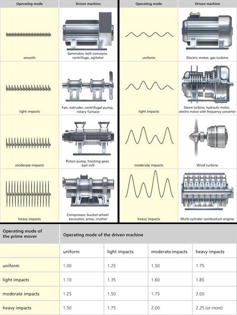
Fig. 5: Classic assessment of application factors /DIN 3990
Figure 5 shows that a driven machine operated uniformly in an application with moderate impacts needs to be designed with 50% higher drive power. This means not only that more powerful drive components must be used, but also that higher costs will be incurred. With respect to vibrations, the dynamic factor is very important in the dimensioning of drive technology. This factor quantifies the permissible torsional load vibrations. For stationary gear drives, a factor of 1.2 is often used. Quantitatively, this means that 20% load variations are permissible – whether they occur stochastically or regularly. More specific information is provided by load spectra for the particular application.
Then the project planner and/or design engineer can dimension the components to the specific application. Whether the load spectrum was determined based on the class boundary method, the rainflow cycle counting method or other counting methods will not be discussed here.
When analyzing loads, research is also required to determine if the respective machine or system is being operated as intended. For example, if products other than those specified are being processed in a rolling mill, or if more powerful motors are being used, measurements should be conducted to analyze whether the machine or system fulfills the necessary safety requirements to withstand the new loads over its required service life.
Load vibrations contain dynamic information
Measuring load vibrations
Mechanical vibrations are caused by the effects of forces that arise within the system or are periodically introduced into the system. Load vibrations are a special form of vibration and permit a dynamic load analysis.
Load vibrations can exert torsional, transversal and axial forces in rotating components and lead to premature fatigue. Other indicators of load vibrations are forces, displacements, deformations, strains and elongations, and require suitable load measurements.
This paper is limited to torques in rotating shafts. Torque measurements are useful for the following types of applications:
- Torque measurements to boost power and performance
- Torque measurements to describe and monitor the operating and functional behavior
- Detection of critical load conditions and overloads with “before and after” documentation
- Torsional vibration documentation and analysis on the basis of dynamic torque analyses
- Torque measurements to determine load spectra and to monitor load responses
- Most valuable troubleshooting tool in analyzing the causes of damage
Measuring torques, with examples
Torque measurement as a tool for boosting performance
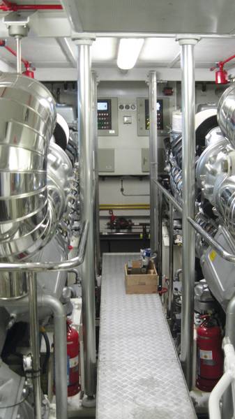
Fig. 6: showing the engine room
A 38-m charter yacht (Figure 6) was unable to reach its desired speed. Starting at a certain load level, secondary vibrations could be felt in the hull. It was suspected that cavitation was occurring and that the propellers were unsuitable for the hull.
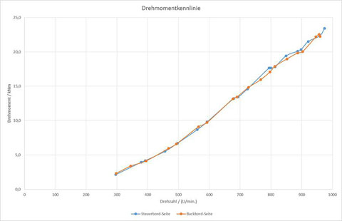
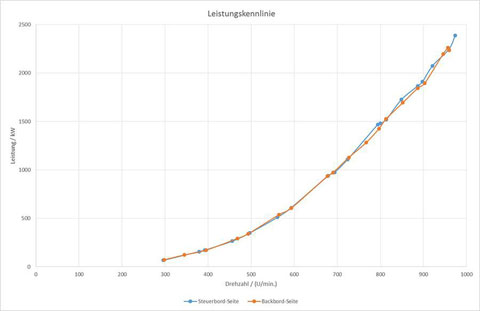
Fig. 7: Propeller characteristics of both drives
PRÜFTECHNIK was commissioned to conduct torque measurements to analyze the cause of the load vibrations and determine the propeller characteristics. For this purpose, strain gauges were applied on both the port side and starboard side propeller shafts; also, two telemetry systems were mounted and a mobile VIBXPERT was used to measure static and dynamic torques in recording mode. Figure 7 shows the analyzed propeller characteristics for the motor output and the torque for both sides. The following conclusions can be drawn:
Both motors operate at a similar load level. Both the port and starboard motors are evenly adjusted. There is no “turbo lag”.
Neither motor reaches its rated output, which confirms that the propellers are not suitable for the hull. The propeller characteristics make it possible to determine which alternative propellers would be effective. Whether the number of blades should also be changed is left to the discretion of the propeller manufacturer. Detailed analyses showed that the port side achieves a lower output.
Analyses of the dynamic torques showed that one blade of the 4-blade propeller on the port side was projecting. This caused additional load vibrations, which at maximum speed even resulted in initial signs of cavitation. The affected blade was the one just after the attached speed marker, which can easily be identified by the “propeller blade pattern” after removing the propeller.
Torque measurement as a tool for analysis of the operating and functional performance
A manufacturer of a mobile grain mill wanted to know which static and dynamic loads existed in his vehicle under typical and atypical process conditions and where potentials for improvement might be found. For this purpose, strain gauges were applied at several measurement locations on the vehicle and the operating behavior was analyzed to determine any undesired load vibrations.
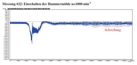
Fig. 8: Example of an operating state
Figure 8 shows an example of a time signal of the torque when the hammer mill was switched on and views of two torque measuring locations.
Torque measurement for identifying critical load situations
In a power plant drive system, inexplicable gear tooth damage occurred in a
gearbox. Based on systematic damage analyses, the occurrence of overloads
was suspected. Torque measurements were conducted to determine whether
the start-up or switching processes in the pole-changing motors were responsible.
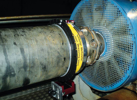
Fig. 9: View of the measurement location on the gear side
Figure 9 shows a view of the measurement location near the gearbox. In the torque signals, three torsional natural frequencies can be identified. A soft starter was retrofitted to reduce the excessive amplitude of the first torsional natural frequency directly after start-up.
Torque measurements for calculation of torsional vibrations
According to torsional vibration calculations, a variable speed pump unit was subject to resonance at certain speeds.
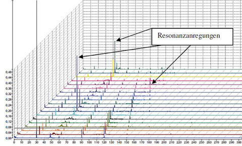
Fig. 10: Campbell diagram of the torques during progressive start-up of the pump unit
Are modifications necessary? How exact are the simulations for this new machine? Which amplitudes occur in the application? PRÜFTECHNIK was commissioned to conduct systematic torsional vibration analyses. Torque measurements at different RPMs made it possible to validate the calculated natural frequencies for the specific frequencies. Figure 10 shows an example of this type of Campbell diagram for torques up to 300 Hz. Based on this representation, it was possible to make the load amplitudes of the torsional vibrations available to the calculation engineer to enable him to further adjust the torsional vibration model. These results were also used to specifically hide the torsional vibrations at 48 Hz.
Contact:
Anne-France Carter
Tel.: +4-89-99616-235
Email: anne-france.carter@pruftechnik.com
PRÜFTECHNIK AG
Oskar-Messter-Str. 19-21
85737 Ismaning, Germany
Tagged analysis, load measurement, Prüftechnik

Pingback: get social signals
Pingback: the future of bitcoin
Pingback: GVK Biosciences
Pingback: Petplay
Pingback: netherland seedbox